


The 433 MHz RF Signal Strength Detector is a circuit designed to sense and measure the intensity of radio frequency signals in the 433 MHz ISM band. This band is commonly used by devices such as wireless modules (e.g., HC-12), RF remote controls, wireless doorbells, and IoT transmitters.
The circuit explained in this documentation is a simple RF Strength Detector that visually represents the strength of RF signal. This circuit works on 433MHz frequency and can be made inside a small box enclosure which can be used in industries as a tester for newly made devices such as TV remote controls, RF transmitters, car keys, which use the same frequency band of 433MHz. It can also be used to check whether the battery of the transmitters are running low. Apart from this, building this circuit is highly beneficial for learning how RF systems work.
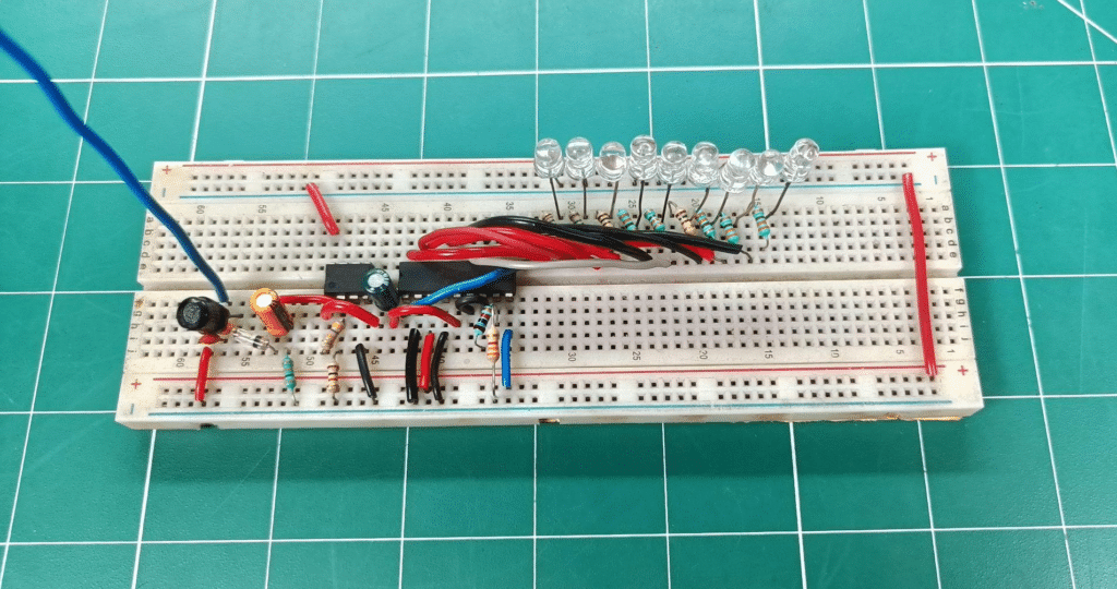
This intermediate-level project is cheaper to build on a breadboard as it does not use any microcontroller or uncommon ICs, and materials. With a few basic RF and Analog Electronics concepts, anyone can make this project easily.

Circuit Description
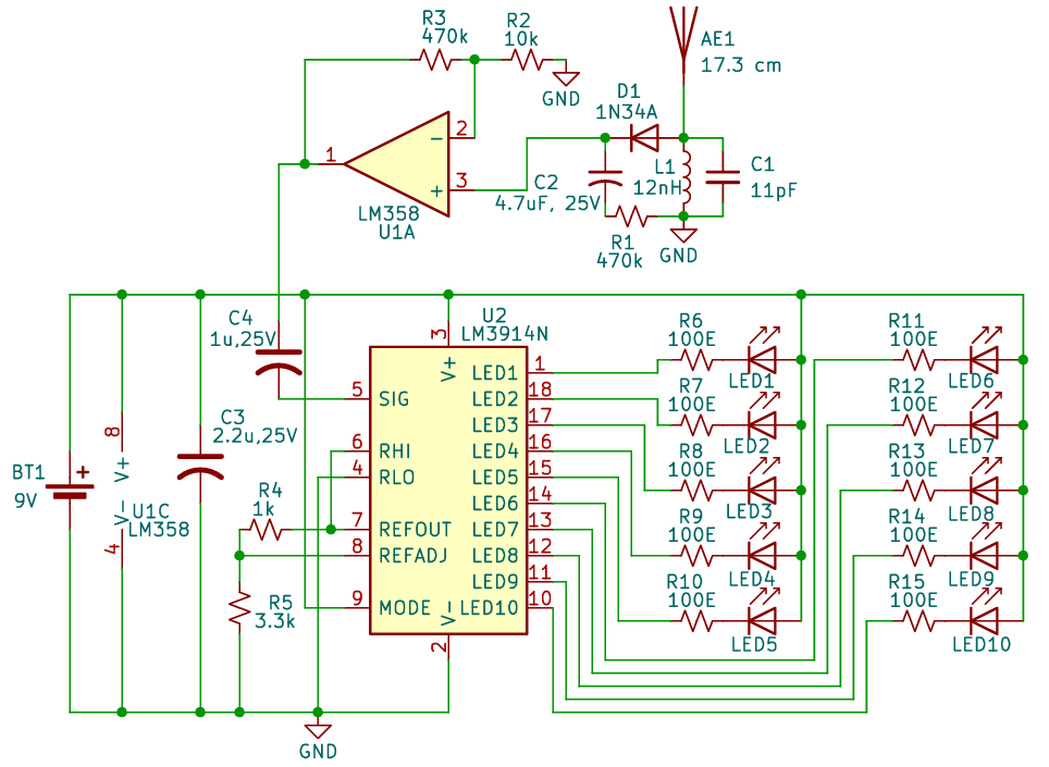
This circuit includes a signal detection part, which uses an antenna or a jumper wire of length 17.3cm(approximately), LC oscillator configured for approximately 430MHz to 438MHz, a germanium diode with very low cut-off voltage (0.2V – 0.3V) which converts the signal bursts into a measurable DC voltage. And a capacitor-resistor network to smooth out the input from the antenna.
The output from the detector goes into an operational amplifier, which is configured with a gain of 48, which can also be changed by changing the values of feedback resistors. Now, the amplified output from the op-amp goes to pin 5 of LM3914, which is used to drive LEDs according to the signal amplitude. LM3914 can be configured in two ways: one to display output as a single dotted pattern or as a bar graph. In this circuit, it is configured to display the spectrum as a bar graph for a better visualisation, i.e., by making pin 9 high.
| Parts List |
| Semiconductors U1 – LM358 dual op-amp U2 – LM3914N LED display driver IC D1 – 1N34A germanium diode LED1–LED10 – 5mm LEDs (any colour as desired) Resistors(All ¼-watt, 5% carbon film) Capacitors Miscellaneous |
Circuit Diagram
Working
The input is taken from a 17.3 cm antenna in the form of small signal bursts, connected with 433MHz tuned LC circuit for amplification of the signal, then the amplified signal is passed to 1N34A germanium diode which converts those signal bursts into a measurable DC voltage, which is sent to LM358 op-amp. The amplified output from the op-amp is then transferred to LM3914 display IC’s input which showcases the LEDs as a bar graph according to the signal strength.
For testing, a 433MHz RF transmitter module is used. It is to be noted that this circuit is made on a breadboard which is prone to noise signals due to internal connections of the breadboard, but it can work and can be used for learning purposes. For more precision, a PCB is preferred with closely connected components. This circuit works on a high frequency which is very sensitive to even small noise signals, especially from the common ground/earthing. So it is recommended to use a standalone 9V battery instead.
Learning points
- Learn to make an RF signal detector using LC circuit and discrete components.
- Learn the concept of gain in an op amp.
- Learn to visualise analogue signals using LEDs without digital processing.
- Develop practical debugging skills and awareness of noise and grounding issues in analog circuits.