

There are a lot of automatic pump controllers and water-level monitoring systems out there. But the moment you look for something wireless with proper IoT features, where you can see the tank’s water level in real time and switch the pump on or off from your phone or laptop, the prices shoot up to around ₹5,000–₹6,000. Most of them are also pretty bulky and come in those big box-type enclosures.
So instead, we’re putting together a much simpler and cleaner solution. It’s super compact (under 4 cm), easy to fix on a tank, and does everything you actually need: pump control, real-time alerts, and accurate level readings. You also get a neat dashboard for all the controls, and the device works in both WiFi AP mode and STA mode. That means you can either connect directly to it or let it join your home network.
To keep the device small and easy to install, we’re using the IndusBoard Coin V2. It gives us enough I/Os and an ADC to measure the water level properly. For controlling the pump, we’re pairing it with a relay module so the switching stays safe and reliable.


Note: In the Bill of Materials, instead of the 5V power adapter, you can also use a 5V battery along with a small solar panel to make the device independent of electricity.
Connections
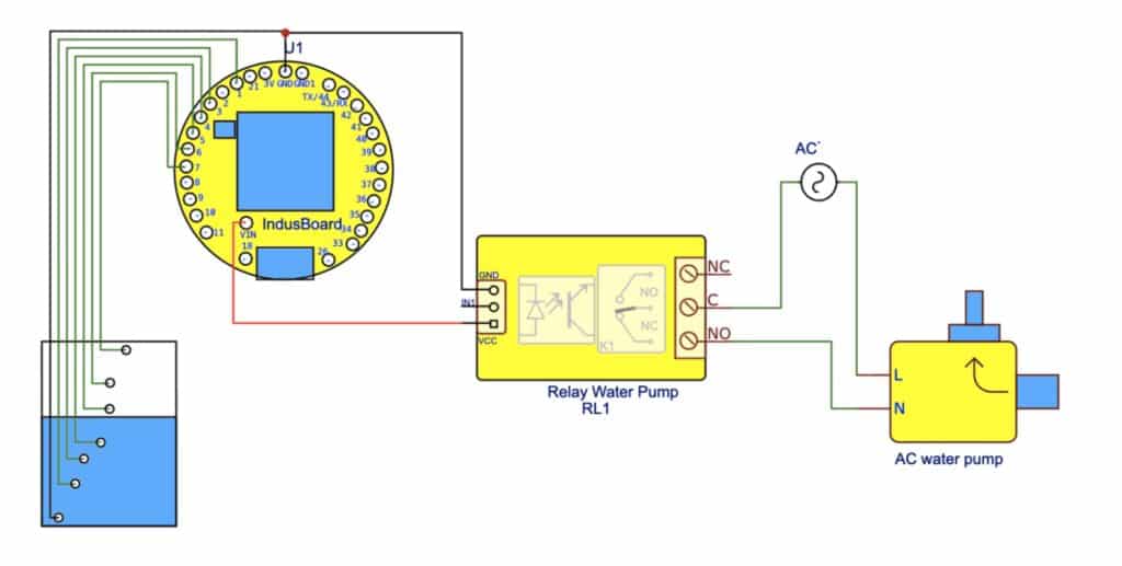
Start by connecting all the components as shown in the circuit diagram (Fig. 2).
For power, connect the 5V pin of the IndusBoard to a 5V power adapter, and make sure the GND pin of the IndusBoard is tied to the common ground of the entire circuit.
Water Level Sensing (Conductive Probes)
Common GND Probe:
Attach a wire to the GND pin of the IndusBoard and place it at the bottom of the tank. This will act as the reference probe.
Level Probes:
Connect GPIO pins 1, 3, 4, 5, 6, and 7 to individual wires placed at different heights inside the tank (0%, 20%, 40%, 60%, 80%, 100%). When the water reaches a particular height, it will complete a path to the GND probe, allowing the system to detect the water level.
Note: You don’t need external resistors because the ESP32-S2’s internal pull-ups will be used (configured in the code).
Relay Module for Pump Control
- VCC: Connect the relay module’s VCC to the 5V pin of the IndusBoard.
- GND: Connect the relay module’s GND to the IndusBoard’s GND.
- Signal (IN): Connect the relay’s signal pin to GPIO 33 of the IndusBoard. This pin will control the pump’s ON/OFF state.
Pump Wiring:
Connect the 220V AC pump to the relay’s Normally Open (NO) and Common (COM) terminals. Make sure the live (L) and neutral (N) from your 220V supply are wired properly between the relay and the pump.
If you’re unsure about handling AC mains wiring, consult an electrician—safety comes first.
Code
Now, let’s move into the coding part, written in the Arduino IDE. This assumes you already have the ESP32 board package installed and everything ready to go.
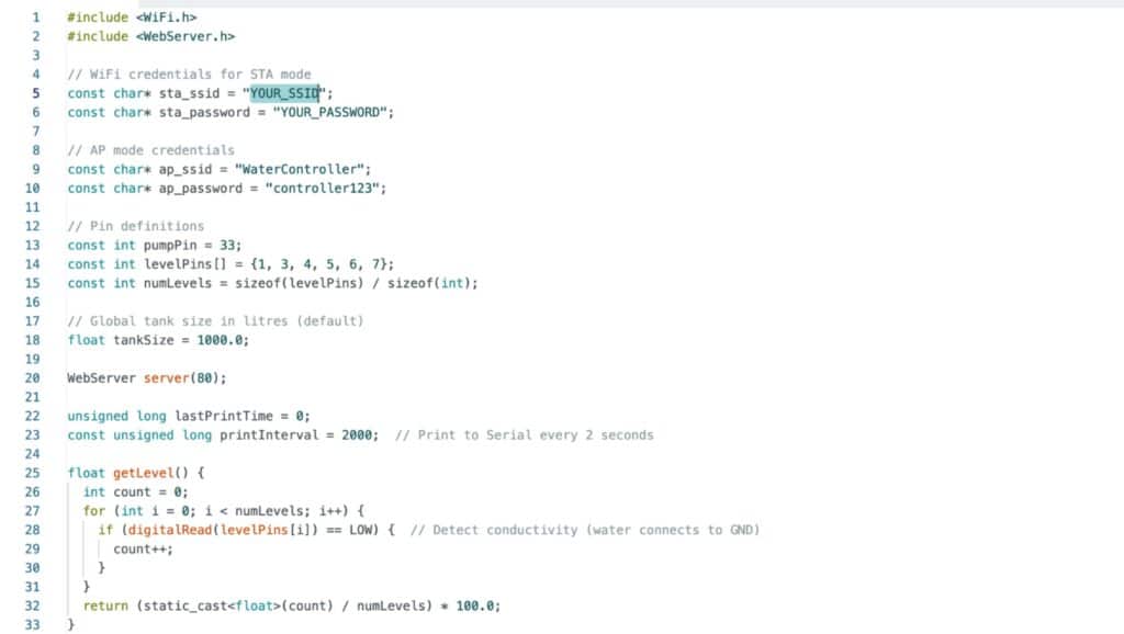
The code begins with an array of I/O pins for water-level detection:
const int levelPins[] = {1, 3, 4, 5, 6, 7};
These six pins correspond to the conductive probes placed at different heights inside the tank, covering levels from 0% to 100%.
After that, the Wi-Fi configuration comes in. STA mode is set up using:
const char* sta_ssid = "YOUR_SSID";const char* sta_password = "YOUR_PASSWORD";
You just need to replace these placeholders with your own Wi-Fi name and password so the device can join your home network.
For flexibility, AP mode is also included:
const char* ap_ssid = "WaterController";const char* ap_password = "controller123";
This allows you to connect directly to the device, which is helpful when running it in standalone mode.
In the setup section, the web server is started, and the I/O pins are configured as input pull-ups for water-level detection using the conductivity method. After that, different functions are added to handle water-level calculations, pump control, and the other required operations.
Testing Water Level Monitoring and Pump Control System
Now place the device on top of the tank and position the wires at their respective levels. Power it on, and you can connect to it either through its hotspot (using the name and password you set in the code) or through your home Wi-Fi, if it has already joined the network.
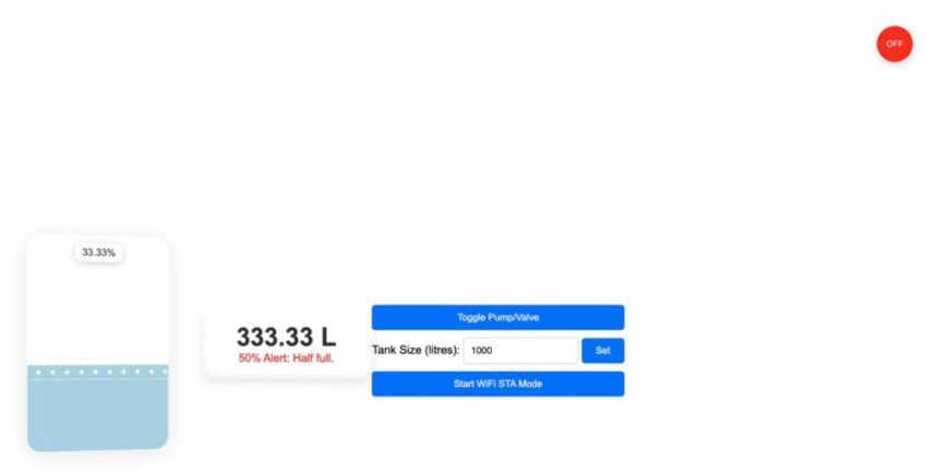
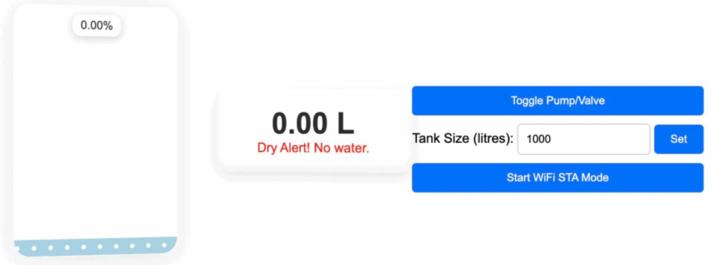
Once connected, open a web browser, enter the device’s IP address, and you’ll be able to see the real-time water level. In the webpage UI, set the total capacity of your tank in liters and submit it. The system will then estimate the amount of water based on the detected level.
For pump control, you can switch the pump ON and OFF from the interface. The floating circle at the top will change color—green for ON and red for OFF—so you can easily see the pump’s current status.