


Designing a circuit to switch on a light at dusk and off at dawn is straightforward, and many such designs have been featured in EFY. However, lights controlled this way remain on all night, resulting in wasted electricity and reduced lamp lifespan. In most homes and business premises, outdoor lights are turned on at dusk and switched off after a few hours. The device described here automates this process, activating the light in the evening and switching it off after 2 to 6 hours. This approach is particularly effective for securing locked homes, as the timed lighting creates the illusion of occupancy and deters potential intruders.

| Parts List |
| Semiconductors: IC1 (IC1A, IC1B) – LM358 dual op-amp T1 – 2N3904 NPN transistor D1-D5 – 1N4007 rectifier diode LED1, LED2 – 5mm LED Resistors (all 1/4-watt, ±5% carbon): R1, R2, R6, R8 – 10kΩ R3 – 4.7kΩ R4, R7 – 1kΩ R5 – 560Ω Capacitors: C1 – 1F, 2.7V super capacitor C2 – 220µF, 25V electrolytic Miscellaneous: CON1-CON3 – 2-pin connector Batt.1 – 12V battery/12V adaptor RL1 – 12V, SPST relay LDR1 – Small light-dependent resistor – 60-watt bulb for lamp |
Circuit and working
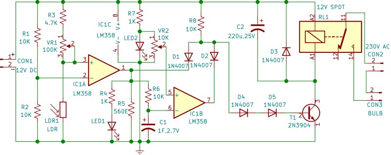
Fig. 2 shows the circuit diagram of the automatic evening light. It is built around the dual op-amp IC LM358. The first op-amp, built around IC1A, is used as a comparator. The inverting pin 2 of the comparator is biased at half the supply voltage by resistors R1 and R2. During the daytime, the resistance of the LDR connected to the non-inverting pin 3 of the comparator is low. The voltage at the non-inverting pin 3 is lower than the voltage at the inverting pin 2, so the output at pin 1 of the comparator is low.
In the evening, the resistance of the LDR increases and becomes more than the resistance of R3 plus VR1, and the output at pin 1 of the comparator becomes high (that is, about 1.5 volts below the supply voltage). Potentiometer VR1 serves as sensitivity control.

The second op-amp is built around IC1B of IC LM358. Its inverting input pin 6 is connected to supercapacitor C1. Resistor R4 and LED1 drop the output of comparator IC1A at pin 1 to the forward voltage of LED1, which is about 2V. This voltage is used to charge the supercapacitor through resistor R6. This protects the supercapacitor from damage due to high voltage and ensures that it is charged at a constant rate, irrespective of supply voltage fluctuations.
The non-inverting input pin 5 of the second comparator IC1B is connected to the forward voltage of LED2 through potentiometer VR2. LED2 also acts as a power-on indicator. Initially, the supercapacitor C1 is discharged, and the voltage at the non-inverting input pin 5 is higher than the voltage at the inverting input pin 6, so the output at pin 7 of the second comparator IC1B is high.

Thus, in the evening, the outputs of both comparators IC1A and IC1B are high. The outputs of both comparators are applied to transistor T1 through diodes D1 and D2 and pull-up resistor R8, which function as an AND gate. This conducts the transistor T1 to switch on the light through the contacts of relay RL1.
After a few hours, the voltage at supercapacitor C1 exceeds the voltage applied to the non-inverting pin 5 of the second comparator, and the output at pin 7 becomes low. This cuts off transistor T1 and switches off the light. The output of the first comparator remains high and LED1 continues to glow, and C1 continues to charge.
In the morning, the output of the first comparator also becomes low and LED1 turns off. Super capacitor C1 now begins discharging through R6 and R5. By the evening, C1 is fully discharged, and the circuit is ready again for the next operating cycle. R5 is essential to ensure that C1 discharges even when the power supply is on. The device does not need to be reset in the daytime and will continue to switch on the light every evening for a few hours without human intervention in a locked house.
Experimentally, it has been observed that the output of the comparators, when low, is not zero volts. A small voltage—about 0.8 volts—exists at the output of the comparators when the output is low. Due to diodes D1 and D2, which form part of the AND gate, the voltage at the junction of the anodes of D1, D2, and D4 is around 1.3 to 1.4 volts, even when the output of either comparator is low. This is sufficient to turn on transistor T1. Hence, D4 and D5 are connected in the base circuit to absorb this voltage and ensure that the transistor conducts only when the output of both comparators is high.
Construction and testing
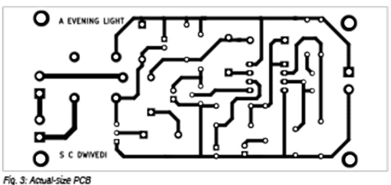
An actual-size, single-sided PCB layout for the automatic evening light is shown in Fig. 3, with its component layout in Fig. 4. After assembling the circuit on the PCB, enclose it in a suitable box, positioning all the switches and LEDs on the top of the box. Fix the LDR on the top of the box. Mount CON1 on the front side of the box. Mount CON2 and CON3 on the back side of the box. The device can also be assembled on a general-purpose board or a Veroboard.
Keep the wiper of VR2 towards the anode of LED2 so that about 2 volts are applied to the non-inverting input of IC1B. In the evening, adjust VR1 so that LED1 and the lamp turn on. After a few hours, adjust VR2 so that the light switches off.

Cut-off time calibration
The output of comparator IC1A will be high in darkness. The output of comparator IC1B will remain high as long as the voltage at C1 is lower than the voltage at the wiper of VR2, which is connected to pin 5 of IC1B. The supercapacitor C1 will charge to 63.2% of the LED1 voltage (2V), which is approximately 1.264V, after 10,000 seconds (or 2 hours and 47 minutes), and to 86.5% of the LED1 voltage (approximately 1.73V) after 20,000 seconds (or 5 hours and 33 minutes).
Therefore, the duration for which the lamp remains on can be set by adjusting the voltage at the wiper of VR2. For example, to switch the light off 2 hours and 47 minutes after it turns on in the evening, set the voltage at pin 5 of IC1B to 1.264V using VR2. This enables the calibration of the switch-off time between 2 to 6 hours using VR2.
Pradeep Vasudeva is a member of the Indian Forest Service, presently posted as Director, State Forest Research Institute, Jabalpur. Electronics has been his passion since adolescence, and his areas of interest include amateur radio, RF circuits, and audio projects.